|
LemLib
0.4.7
An easy to use and feature-rich PROS template
|
|
LemLib
0.4.7
An easy to use and feature-rich PROS template
|
Welcome to the third LemLib tutorial! In this tutorial, we will be learning how to tune the PIDs, move the robot, and use odometry.
As mentioned in the previous tutorial, LemLib uses odometry to track the position of the robot. However, we need to calibrate it at the start of each match. To do this, we need to call the chassis.calibrate() function in initialize() Below is an example of how to do this:
Note that the chassis should be stationary when you call this function. It will take 3 seconds to calibrate, so don't be alarmed if it doesn't seem to be doing anything.
Pretty simple, right? Now, we can use the chassis.getPose() function to get the current position of the robot. It returns a lemlib::Pose object, which contains the x, y, and heading. The code below uses the chassis.getPose() function to print the current position of the robot to the brain screen:
We can also set the position of the robot using the chassis.setPose() function. Below is an example of how to do this:
LemLib has 3 functions for moving the to. We will be covering the first 2 in this tutorial, and the third in the next tutorial.
The first function is lemlib::Chassis::turnTo. This function turns the robot so that it is facing the specified (x, y) point. It takes between 3 and 5 arguments. It uses the PID gains specified in the lateralController struct. Below is an example of how to use it:
As you can see, using this function is very easy. The first 2 parameters are the X and Y location the robot should be facing. The third parameter is the timeout, which is the maximum time the robot can spend turning before giving up. The fourth parameter is whether the back of the robot should face the point (true) or the front of the robot should face the point (false). It defaults to false if not specified. The fifth parameter is the maximum speed the robot can turn at. If you don't specify a value for this parameter, the robot will turn at full speed.
The second function is lemlib::Chassis::moveTo. This function moves the robot to the specified (x, y) point. It takes 3 or 4 arguments. It uses the PID gains specified in the lateralController and angularController struct. Below is an example of how to use it:
This function is very similar to the chassis.turnTo() function. The first 2 parameters are the X and Y location the robot should move towards. The third parameter is the timeout, which is the maximum time the robot can spend turning before giving up. The fourth parameter is the maximum speed the robot can move at. If you don't specify a value for this parameter, the robot will move at full speed.
Now that we know how to move the robot, we can start tuning the PIDs. Let's start with the lateral PIDs.
The lateral PID is just a simple PD controller, with some minor optimizations. When we tune the lateral PD, we want the kP as high as possible with minimal oscillation. But how do we change these gains? The answer is the lateralController struct we created in the previous tutorial. Here is a reminder of what it looks like:
The first 2 parameters are the kP and kD gains. These are the ones we will be focusing on for now. When we tune them, we want kP as high as possible with minimal oscillation (the robot moving backwards/forwards repeatedly at the end). Here is the algorithm we will be using to tune these gains:
chassis.moveTo() functionAfter this, you need to tune the slew rate. This controls the maximum acceleration of the chassis in order to prevent tipping. To tune it, simply increase it until the robot starts tipping too much. Higher values make the robot accelerate faster, and slower values make the robot accelerate slower.
The process for the angular PID is very similar. Here is a reminder of what the angular PID looks like:
Here is the algorithm we will be using to tune these gains:
chassis.turnTo() functionYou may have noticed that there are 4 more values in the angularController and lateralController structs. These are values for the timeouts. Here is how they work:
smallErrorRange is the range of error that is considered "small". If the error is within this range for smallErrorTimeout milliseconds, the robot will proceed to the next movementlargeErrorRange is the range of error that is considered "large". If the error is within this range for largeErrorTimeout milliseconds, the robot will proceed to the next movementThe units for error in the chassis.moveTo() function are inches, and degrees for the chassis.turnTo() function. The units for time are milliseconds.
Advanced users may wish to alter these values to decrease the time it takes to execute the next command. However, the default values should be fine for most users.
Another project we have been developing is the Path Generator. This web app allows you to create a path for the robot to follow using pure pursuit, which will be covered in the next tutorial. For now, we will be using it to view coordinates on the field.
When hovering your mouse over a location on the field, its coordinates will be displayed in the bottom left corner. You can then manually input these coordinates into the chassis.moveTo() and chassis.turnTo() functions. You can also view the starting position of the robot by simply hovering your mouse over where it would start. You can set the position of the robot by using the chassis.setPose() function, as documented in tutorial 2. Below is an image of the Path Generator:
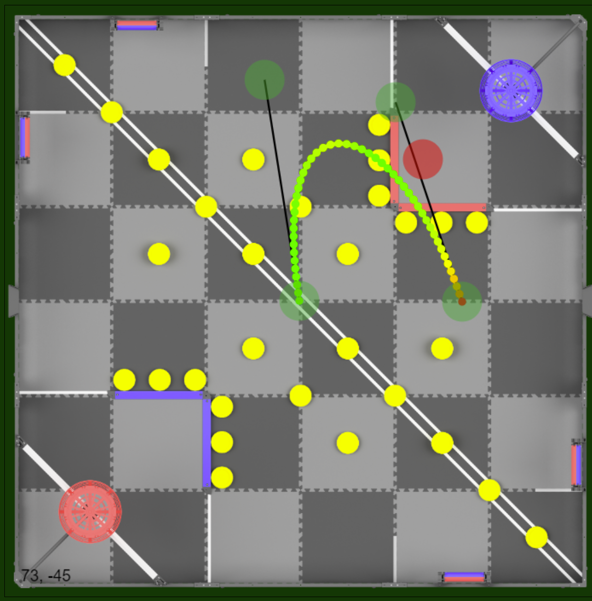
Note that the origin of the field is in the middle, and the field coordinates are measured in inches. 0 degrees is facing up, and increases clockwise.
Thats it! You now know how to move the robot around the field using the chassis.turnTo() and chassis.moveTo() functions. In the next tutorial, we will be covering how to use the Path Generator to create a path for the robot to follow.